



How Can Electromagnetic Flowmeters Improve Flow Measurement Accuracy?
Reliable flow data supports water balance, process control, leakage assessment and operational reporting. When readings change unexpectedly, engineers need to know whether the network has changed or the measurement point is producing unreliable information. That confidence depends on selection, installation, configuration and verification.
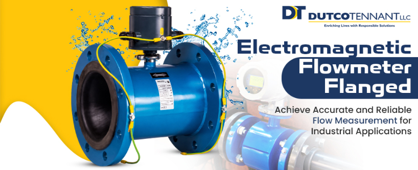
Electromagnetic flowmeters measure conductive liquid by applying a magnetic field across the pipe and detecting the voltage created as the liquid moves through it. With no moving measuring components in the flow path, they can provide stable, bidirectional measurement with negligible hydraulic restriction. We still need to match the meter and its installation to the actual duty. Accuracy is the result of a complete measurement chain, not a specification value viewed in isolation.
Confirm that the liquid can be measured correctly
The electromagnetic principle suits conductive liquids. This makes an electromagnetic water flow meter relevant to potable-water distribution, wastewater, irrigation and many industrial water duties. It is not the correct starting point for every fluid, so conductivity, temperature, pressure and chemical compatibility should be checked before a model is selected.
Material selection is part of this review. The liner remains in contact with the process liquid, while the electrodes detect the induced signal. Their materials must suit the water chemistry and operating conditions. The reviewed flanged range provides different flowtube, flange and electrode material options, allowing us to coordinate the sensor construction with the intended service rather than treating all water applications as identical.
Keep the measuring tube full
An electromagnetic meter calculates flow from liquid velocity and the known internal cross-section of the measuring tube. The electrodes therefore need continuous contact with the liquid. A partially filled pipe, trapped air or an unsuitable installation position can interrupt that condition and produce unstable or misleading readings.
We review pipeline elevation, pump operation and the possibility of drainage when the system stops. Locations immediately upstream of a free discharge or at a high point require particular care. Where the selected sensor includes empty-pipe detection, the function can help identify loss of electrode contact, but it does not correct a poor hydraulic layout. The installation should create a reliably full measuring section during the operating states that need to be recorded.
Select the diameter around the operating flow range
Matching the flange size to the existing pipe is only the first step. The expected minimum, normal and peak flows determine the velocity that the sensor will see. If a meter is too large for the real duty, low flows may sit near the lower end of its useful range. If it is too small, velocity and headloss conditions may become unsuitable at peak demand.
This is especially important where night flow or seasonal demand is used to identify changes in a distribution network. The MUT2300 electromagnetic flowmeter is designed to measure low velocities, with official documentation stating measurement down to 0.015 m/s in the referenced certified configuration. Its paired technical datasheet states accuracy of 0.2% plus or minus 2 mm/s under the defined conditions. We use such figures with the approved sensor and converter combination, relevant size, configuration and calibration documentation.
A realistic flow profile also improves procurement. Rather than selecting a mag flowmeter from a single maximum-flow value, we can check whether it will represent the complete operating range that engineers and operators need to understand.
Control disturbances at the chosen location
Bends, valves, pumps and changes in pipe diameter can distort the velocity profile entering a meter. Many conventional installations use upstream and downstream straight lengths to allow the flow to settle. The reviewed flanged sensor uses a shaped measuring tube designed for U0-D0 installation, meaning zero nominal pipe diameters of straight length are required upstream and downstream under its stated approved conditions.
This feature can help in chambers and plant rooms where space is restricted. It should not be read as permission to ignore the installation manual. We still confirm flow direction, flange alignment, gasket placement, bolt loading, accessibility, grounding, cabling and any model-specific restrictions. The selected configuration and applicable approval determine which installation claim can be used on the project.
Protect the electrical signal and converter setup
The voltage detected by the electrodes is small, so stable grounding and correct cable treatment support dependable measurement. Earthing arrangements should follow the product instructions and account for the pipe material, lining and nearby electrical equipment. Cable glands, seals and terminal enclosures also need protection suited to the installation environment.
Converter settings shape the information seen by the operator. Damping can steady a rapidly changing display, while low-flow cut-off can suppress signals below a configured threshold. Poorly chosen values may hide genuine low demand or make a fluctuating process look smoother than it is. During commissioning, we document the units, pipe size, flow direction, cut-off, damping, outputs, alarm settings and totaliser configuration.
For a remote flanged electromagnetic flow meter, sensor and converter cable requirements deserve the same attention. Route length, shielding, separation from power cables and enclosure location should match the approved instructions. A sound sensor cannot compensate for an unsuitable signal installation.
Use calibration as the starting reference
Factory calibration establishes how the instrument performs under controlled reference conditions. The reviewed MUT2300 documentation states that each meter is wet calibrated by direct volume comparison and supplied with an individual calibration certificate. That certificate should be linked to the model, serial number, size and project tag during handover.
Commissioning then checks the installed system. We confirm that the displayed direction agrees with actual flow, the pipe is full, the zero condition is credible, outputs reach the control system correctly and totalisers use the intended units. Comparison with pump curves, reservoir level changes or another accepted reference can reveal configuration or integration errors, although these checks do not replace formal calibration.
Preserve confidence after handover
No moving parts means there is little mechanical wear within the measuring tube, but the measurement point still benefits from planned checks. Coating on electrodes, changes in conductivity, damaged cables, moisture at terminals or altered converter settings can affect performance. Periodic inspection and trend review help teams identify these changes before questionable data enters reports or control decisions.
Where suitable verification tools are available for the selected configuration, in-situ checks can assess the electronic and sensor condition without interrupting the process. We recommend retaining the factory certificate, commissioning settings, verification results and change history as one instrument record.
Turn accurate readings into usable evidence
Flow accuracy improves when the liquid, pipe condition, velocity range, installation and electronics are treated as one system. A capable sensor provides the foundation, while disciplined engineering protects its performance from design through operation.
We support project teams in reviewing flanged flow measurement duties for water, wastewater, irrigation and industrial applications across the UAE and GCC. By defining the operating range and installation conditions early, we can help select a configuration that produces dependable data for the decisions the network must support.